| Brief Description | |
|---|---|
|
File: \examples\Processing\DebuggingAndTest\HardwareTest\HardwareTest.va |
 |
|
Default Platform: mE5-MA-VCL |
|
|
Short Description An example for hardware self test of DMA, RAM, GPIOs, Trigger and LEDs. This example extensively uses operators of the parameters library. |
|
The example Hardware Test performs a hardware self test.
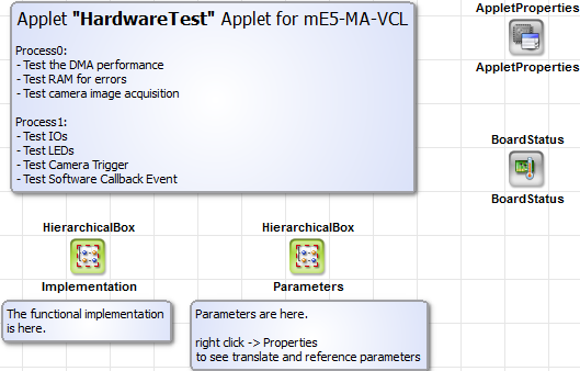
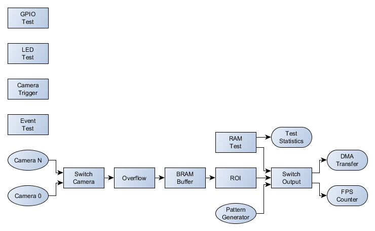
The applet comprises the following functions:
- DMA Performance test: Different image dimensions for varying memory sizes and interrupt rates
- RAM Test: Check for errors and processing
- Camera: Check camera port image acquisition
- Camera Trigger: Send trigger signals to camera
- GPIO: Monitor the GPIs and set the GPOs
- Event test: Generate a sofware callback event
- Monitoring: FPGA Temperature, Power, PoCL, ... (See BoardStatus)
The following diagram shows the functional blocks of the applet.
The VisualApplets implementation is split into two processes. Process0 includes all image processing parts namely the DMA test, RAM test and camera acquisition. Process1 instead includes the parts which are independent of a running acquisition. As processes without DMA operators are immediately started when the applet is loaded, the functions here can be used independently of an acquisition. See 'Processes without DMAs / Trigger Processes' for more information.
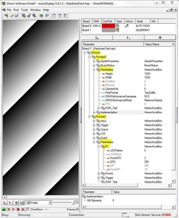
The following two screenshots show Process0 and Process1.
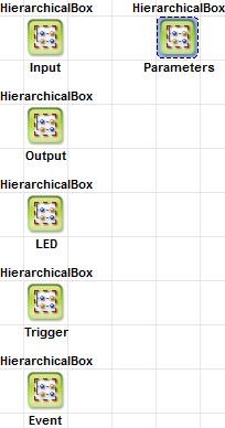
The applet is implemented by intensively using the operators of the parameters library for easy usage of the applet. The H-Box Implementation includes the functional parts. Parameters are listed in the properties of the H-Box Parameters for a separated view. This becomes useful when the applet is used in e.g. microDisplay as only easy to use parameters are listed as can be seen in the next screenshot.
The implementation of the applet is straight forward and can be easly understood by studying the VA file. However, we will have a closer look at some of the parmeter translations and references to understand their usage.
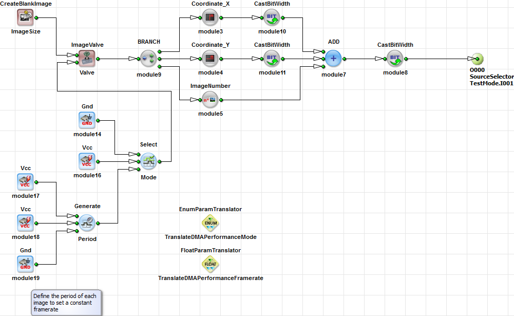
The main image processing part contains the RAM test, DMA perfomance test and camera acquisition. The applet only allows to output one of the modes on a DMA channel at the same time. Thus, several SourceSelector operators are used. To avoid a parameterization specifying the correct input index we use a EnumParamTranslator operator for easy usage.
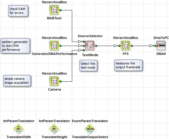
Figure 285. Applet Hardware Test Implementation for RAM Test, DMA Perfomance Test and Camera Acquisition
In the following we describe the parameter values of TranslateOutputSelect in detail.
First, the enumeration values need to be defined.
"DMA_Performance" = 0x001;
"Camera" = 0x002;
"RAM0_Difference" = 0x000;
"RAM0_Errors" = 0x100;
"RAM1_Difference" = 0x010;
"RAM1_Errors" = 0x110;
"RAM2_Difference" = 0x020;
"RAM2_Errors" = 0x120;
"RAM3_Difference" = 0x030;
"RAM3_Errors" = 0x130;
As you can see the values of the enumerations are defined as hexadecimal values. This allows an easy distribution to three SourceSelector modules. The lower four bit are used for module TestMode.SelectSource, bits 4 to 7 for RAMTest/SelectRAM.SelectSource and bits 8 to 11 for RAMTest/SelectRAMOutputMode/EnableBitpattern.SelectSource. This facilitates a very simple implementation for the parameters WriteAction and ReadAction.
The translate value then can be used with the enumeration values. Changing the value will automatically change the parameter values of the SourceSelector modules.
H-Box GeneratorDMAPerformance includes the pattern generator as well as an image valve to controll the output framerate. The pattern generation is very simple using a blank image generator as well as pixel and image counter to generate a rolling diagonal pattern.
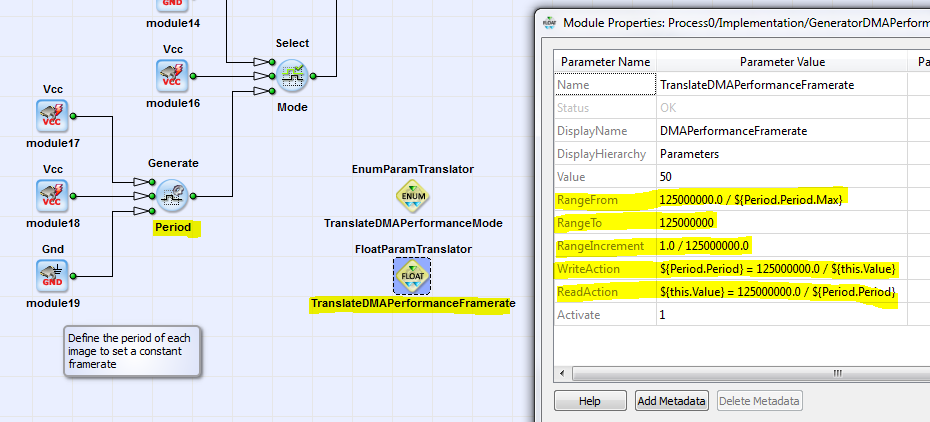
The valve is controlled by a period generator operator Generate. The unit for the generator is given in ticks. As we want to specify a framerate with a time-base, we use translate operator FloatParamTranslator. Thus we use the operator to convert from frames per second to ticks. The following screenshot shows the implementation.
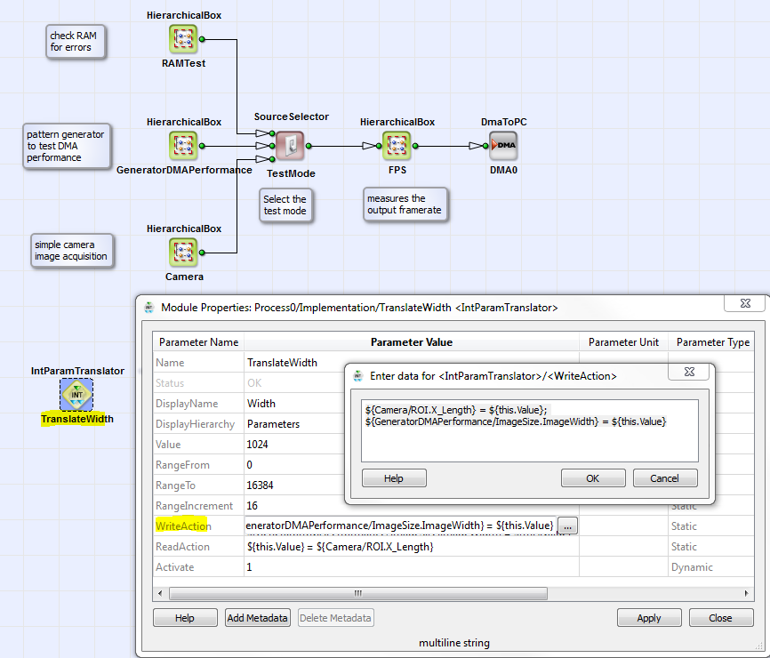
Setting the Width and Height in the Example HardwareTest using operator IntParamTranslator
The same procdeure as shown in the previous sections is done for the image width and height. In this case we can use an operator IntParamTranslator. Here we can directly forward the values to the two modules in the design. Mind the given values for parameters DisplayName and DisplayHierarchy.